The Wipeout button allows to create invisible areas in the drawing.
Quick Access Panel: ![]()
Ribbon: Editor -> Draw -> Wipeout
Menu: Draw -> Wipeout
The Wipeout command is used to hide some parts of the drawing without deleting them. It is an object of the background color, the borders of which have a different color and can be hidden.

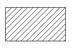
An object

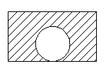
Adding a wipeout

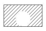
The borders of the wipeout are off
Creating a Wipeout Object
It is possible to create a rectangular and non-rectangular wipeout object. By default a polyline mode is on, which allows to create a non-rectangular wipeout. The submenu of the tool is called by clicking on the black down directed arrow:
•Rectangle. Creates a rectangular wipeout. Is added like the entity Rectangular.
•PolyLine. Creates a non-rectangular wipeout. Is added like the entity Polyline.
•Show. Shows the display of the borders of all the wipeout objects in the current drawing.
•Hide. Hides all the wipeout borders in the current drawing.
To add a non-rectangular wipeout
1. Click on the black down directed arrow on the right of the button ![]() and select PolyLine from the list.
and select PolyLine from the list.
2. Specify the first point of the wipeout object by left clicking in any place of the drawing or via the dynamic input.
3. Drag the cursor aside and left click to select the second point.
4. Right click and select Arc from the context menu to add a circular arc.
5. Drag the pointer and specify the third point of the wipeout object.
6. Right click and select Line from the context menu to add a line segment.
7. Double-click when done.
Editing a Wipeout Object
After being created the element is placed in the foreground. If you need to hide only some of the entities you can specify the corresponding order of drawing with the help of the commands of the context menu Bring to front and Send to back.
The borders of the wipeout object can be changed with the help of markers which appear after its selection. To drag the markers point the cursor at the marker. After the marker changes its color into yellow it can be dragged with the left mouse button pressed.
A wipeout has a set of properties which can be viewed and edited in the Properties panel:
Property |
Description |
|---|---|
Color |
Defines the color of the wipeout object. |
Layer |
Defines the layer which the wipeout belongs to. The property contains a list of all available in the drawing layers and allows to move the wipeout to another layer. |
Line Weight |
Defines the lineweight of the wipeout. Is selected from the standard values. You can turn the function of showing the lines according to their lineweight on or off. Each lineweight value corresponds to a number of pixels on the screen. The number of these pixels isn't changed while scaling in the program window. The scale of lineweighht display on the screen is set in the Visualization tab of the Options window. |
Linetype |
Defines the linetype of the wipeout entity. Is selected from the standard values. |
Linetype scale |
Sets the scale for the current linetype. By default it is 1. |
Point |
Is the base point of modification of the wipeout object, relative to which the sizes are changed with the help of the properties Width and Height. The left bottom angle of the circumsribing rectangle of the wipeout object is referred to as a base point. |
Width |
Is the total width of the wipeout object. For a nonrectangular wipeout this value ie equal to the width of the circumscribing rectangle. |
Height |
Is the total height of the wipeout object. For a nonrectangular wipeout this value ie equal to the height of the circumscribing rectangle. |
Go to CADEditorX