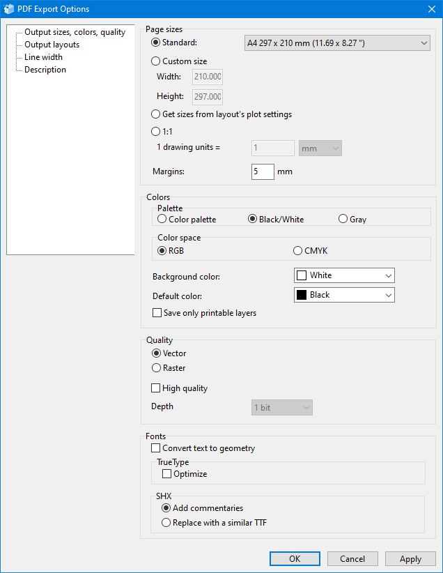
The PDF Export Options dialog box is used to specify options for saving to PDF, such as page size, margins, background color, layouts for saving, line width, document description. There are four groups of settings in the window: Output sizes, colors, quality, Output layouts, Line width, and Description.
The tab includes four groups of parameters. These parameters allow setting page sizes in the output PDF file as well as setting the color scheme and the image quality for the conversion.
Page sizes
Sets the size of pages and the offset from the page edge in the output PDF file.
•Standard. The page size is selected from the list of standard paper formats.
•Custom size. Allows setting the custom page width and height in millimetres or inches.
•Get sizes from layout's plot settings. The page size will correspond to the sizes set in the Plot settings dialog window.
•1:1. Files are converted at a scale of 1:1, i.e. the size of the original file and the output one will be the same.
•Margins. Sets the value of the offset from the edge of the page all over its perimeter. As a result, the area in which the drawing will be placed will be reduced.
Fonts
Sets parameters for font conversion into PDF.
•Convert text to geometry. If the setting is enabled, text won't be saved during its conversion to PDF. It will be transformed into geometric entities instead.
•TrueType. Optimize. If the setting is enabled, the font isn't written to a file completely. Only the characters used in the drawing are written to a file. It allows reducing the output PDF file size.
•SHX. Add commentaries. Adds a commentary for the SHX texts into a PDF file. Texts are saved as geometry.
•SHX. Replace with a similar TTF. If the setting is enabled, texts written with an SHX font are replaced with a similar TTF font.
Colors
Defines the color scheme of the converted CAD file.
•Palette. Sets the color scheme of the CAD file. The vector image can be converted in three color schemes:
- Color palette: the image in the output PDF file corresponds to the colors of the original drawing.
- Black/White: all vector image elements which color differs from black/white become black/white after conversion
- Gray: all vector image elements which color differs from black/white are displayed in grayscale after conversion.
•Color space. The RGB and CMYK options allow selecting the color space that will be used to save colors in a PDF file.
•Background color. Sets the color of the drawing background in the output file. It is applied regardless of the current background color of the workspace.
•Default color. Sets the default line color for the Black/White palette in the drawing.
•Save only printable layers. If the option is active, entities on printable layers are saved to PDF.
Quality
•Vector. Saves the file as a vector PDF file.
•Raster. Saves the file as a raster PDF file. The image depth is set with a corresponding setting.
•High quality. If the setting is enabled, the file is saved with a higher precision. The higher quality is, the larger the output file size is.
Note: 1) Please take into account the fact that while exporting files to PDF, the image is fit to the specified page size with allowance for margins on the larger side. Thus, to get the drawing in the 1:1 format, in the PDF Export Options window, specify Custom size of the file that is equal to the drawing sizes and select zero width margins. 2) if the input file contains a color raster picture, the color settings will be ignored for the raster picture.
The settings on this tab allow selecting the layouts in the original CAD file for their export to PDF.
•Model. Exports the Model layout only.
•All layouts. Exports all layouts of the CAD file except for the Model layout to a single PDF file.
•Layouts by name. Exports the layouts defined by the user. Layout names are specified in the input field with the "|" separator (no spaces).
•All layouts + model. Exports the Model layout and other layouts to a single PDF file.
•Current layout. Exports the current layout of the CAD file.
These settings allow configuring parameters of the lineweight conversion.
•Save lineweight. Turns on/off lineweight in the vector file during its conversion.
•Lineweight scale. Sets the scale factor for lineweight in the vector image during its export to PDF. By default the scale factor is equal to 1, i.e. lineweight is exported with the 1:1 scale.
•Width of zero-width lines. Sets the width with which lines with the zero lineweight (0 mm) will be exported.
•Print styles. Sets the color and lineweight that will be assigned to the object of a particular color during its print.
These settings make it possible to enter additional information about the saved file, such as title, author, subject, and keywords.
Go to CADEditorX
